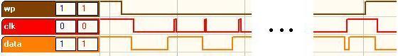
The start and stop conditions of an EEPROM write
This project was tested with Raisonance ver 7.32. The current released version (as of October 2005) is 7.37. It should still work fine.
This article is on the implementation of the I2C protocol. The I2C specification has been defined very well on many web pages and in Philips Semiconductor data sheets (see Philips publication "9398 393 40011", which can be found on their web page at http://www.semiconductors.philips.com/acrobat_download/literature/9398/39340011.pdf), and thus will be discussed very little here. It is assumed the HW is properly attached to dedicated IO pins on an 8051 derivative micro.
Many of the low cost 8051 devices do not have a built-in I2C bus controller, thus programmers are forced to manually "bit bang" their data out to I2C devices. Specifically, this article is about an implementation of a bit-banged master-slave I2C bus with the 8051 as the master, and it assumes that the slave device(s) does not request to have service performed.
Many implementations can be found on the web for doing an I2C master/slave bus. The ones I have investigated are all complete, but are either far more complex than needed, are very inefficient, or have both of these disadvantages. Also, some of the examples are in assembly. While an assembly-based driver is fine, it can be harder to maintain, especially as assembly programming becomes a lost art form and many colleges have removed many (or all) assembly classes from their requirements.
Code and RAM space are VERY valuable.when you are working with memory-limited micros such as the 8051, particularly when they are implemented on cost-sensitive products. While modern C compilers can produce code rivaling the size of the best assembly code (the Raisonance family of 8051 tools contains the best code optimizer I have seen), highly optimized code can be time consuming to debug. For this reason, writing efficient C code to start with may reduce the need for using the optimizer.
Please note that many 8051's are not capable of sending data at the maximum speed of modern I2C devices. I have not implemented Fast-mode's SCLK hold feature. Also, Hs-Mode (High Speed, > 3Mbit) isn't even considered.
bit  I2C_Start(void)
bit  I2C_Send_Byte(unsigned char)
unsigned char I2C_Get_Byte(bit)
bit  I2C_Stop(void)
There is also an initialization function, though unless your project needs anything more specific, it can be defined as a call to I2C_Stop so that the devices on the bus are all in the same state and the clock and data lines are left in a high position.
A basic pseudo-code write operation would be as simple as:
I2C_Start();
I2C_Send_Byte(device_address | I2C_WRITE);
while (there is data to send)
  I2C_Send_Byte(next_byte_of_data);
I2C_Stop();
A basic pseudo-code read operation would be as simple as:
I2C_Start();
I2C_Send_Byte(device_address | I2C_READ);
while (there is data to get)
  I2C_Get_Byte();
I2C_Stop
Obviously, the return values should be checked to make sure there has been no error. Depending on which is more important, you can choose to check for an error after sending/receiving all of your data, or check after every transaction. The former will take less code space and runs the fastest, but you will not detect an error as quickly as if it is checked after every transaction. The later will take slightly more code space, but errors are detected the instant they are made. This solution also will take a little longer to execute, as the conditional will need to be executed every time.
As most I2C transactions are relatively short, time-wise, I generally opt to check at the end.
bool success;

I2C_Start();
if ((success = I2C_Send_Byte(device_address | I2C_WRITE)) == TRUE)
  while (there is data to send)
    success &= I2C_Send_Byte(next_byte_of_data);
I2C_Stop();
if (success == FALSE)
  {
  /*--- do something because of the error ---*/
  }
At the beginning of an I2C start, both the data and clock lines must be high. While the clock line is high, the data line goes low, followed by the clock line. Since under most circumstances the data line should only change when the clock line is low, this signals a special state -in this case, a start condition.
  I2C_DIO = 1;               //data has to be high before the clock
                             //is, this is the definition of a start
  I2C_CLK = 1;
  I2C_NOP();
  I2C_DIO = 0;               //change the data while CLK is high
  I2C_NOP();
  I2C_CLK = 0;
Sending the data is straightforward. This routine should be used to send the I2C bus address (which immediately follows the start), as well as the data being sent to control/configure the I2C device.
  for(index = 0x80; index != 0; index >>= 1)     // MSB first
    {
    if (byte_to_send & index)
      I2C_DIO = 1;
    else
      I2C_DIO = 0;

    I2C_CLK = 1;
    I2C_NOP();
    I2C_CLK = 0;
    }

  /*--- now get the "ack" bit to make sure everything is good ---*/
  I2C_DIO = 1;           // set for input
  I2C_NOP();

  I2C_CLK = 1;           // data can be read when the clock is high
  I2C_NOP();
  ack     = I2C_DIO;     // read the ack bit
  I2C_CLK = 0;

  return(ack == I2C_ACK);// returning ACK bit, an I2C ACK is a 0, so we'll
                         // change it to positive logic to make it easier
When receiving a sequence of bytes from some I2C devices, the last byte may required to have a NACK sent as the last bit instead of an ACK. This inidcates to the device that a sequential read has been completed, and that the next I2C action will be a STOP. You'll need to check the data sheet of your particular deivce to determine if this is required. Most EEPROMs require this.
  I2C_DIO = 1;   // set for a read
  X       = 0;
  for(index = 0x80; index != 0; index >>= 1)     // MSB first
    {
    I2C_NOP();
    I2C_CLK = 1;
    if (I2C_DIO)
      X |= index;
    I2C_CLK = 0;
    }

  I2C_DIO = ack;    // ACK (0) or NACK (1) bit
  I2C_NOP();
  I2C_CLK = 1;
  I2C_NOP();
  I2C_CLK = 0;

  return(X);
Like the start condition, a stop involves manipulating the data line with the clock in the high state. Since errors can occur under normal operations (such as a static discharge into your product), the stop function is a little more complex than the start. If the slave is holding the data line low, it indicates the slave isn't ready for a stop. This could happen if it got out of sync with the master. So while the data line is low, pulse the clock line high until the data line goes high (or rather floats, there should be an external pull-up resistor on the bus that actually makes it go high).
  retry = 9;

  I2C_DIO = 1;                 // set it high so we can use it as an input
  while (retry--)
    if (!I2C_DIO)              // while the data line is low
      {                        // continue to pulse the clock
      I2C_CLK = 1;
      I2C_NOP();
      I2C_CLK = 0;
      }
    else
      {                       // when the data line actually is high
      I2C_DIO = 0;            // we can now execute a valid STOP
      I2C_NOP();
      I2C_CLK = 1;
      I2C_NOP();
      I2C_DIO = 1;
      return(TRUE);
      }
  I2C_CLK = 1;
  return (FALSE);             // stop state has failed.
sbit I2C_CLK = P1^6;
sbit I2C_DIO = P1^7;
These should be changed to the appropriate port pin of your project.
Depending on the speed of your 8051 and the devices on your I2C bus, you may also need to change the number of NOPs between transitions. Most 8051 devices that don't have reduced clock cycles will be running slow enough to be below the low-end speed of 100 Kbits/second of a standard I2C device. However, most modern I2C devices operate at higher speeds of up to 400Kbits/second and higher. Regardless, please read the I2C device data sheets in your design to determine if you need to slow down your I2C bus.
A common 8051 will do one SET/CLR instruction in 12 clock cycles. To make the math easy, lets assume the design is using a 12MHz oscillator, thus running at an equivalent of 1MHz. At one megahertz, each machine cycle will be 1 microsecond, and thus many instructions will execute in 1 microsecond. This is a maximum transmission of 500Kbits/second, if we did nothing but SETB and CLR instructions. More realistically it is around 100KHz with all the other overhead.
#define I2C_NOP() (_nop_();)you can easily change this to do multiple NOPs, such as:
#define I2C_NOP() (_nop_();_nop_();)or even entire remove any NOPs from the code by just:
#define I2C_NOP()
Perhaps the first device that I needed to communicate with over an I2C bus was an EEPROM, one of the more complex devices that I commonly use on an I2C bus. Many other devices are just "set and forget" type devices (like a display controller). This exact same I2C code has also been used on display controllers, analog to digital converters, digital to analog converters, CD transports, and many other devices.
The examples shown are for devices with 2 bytes in the memory address field (not to be confused with the device address of the I2C bus itself). Some smaller devices only use one byte in this field. Modifying the code for your purposes should be pretty easy. I have used these routines with 24C32, 24C64, 24C128, 24C256, and 24C512. While most I2C EEPROMs will work with the code given below, please check the data sheet of your specific device. To make your design works, the change may be as simple as modification of one of the #define's in eeprom.h to reflect the proper block size of your device. You may also have to change the write protect pin definition and the address of the EEPROM.
/*--- HW definitions ---*/
sbit EEPROM_WP = P1^5;
#define EEPROM_ENABLE_WRITE()     (EEPROM_WP = 0)
#define EEPROM_DISABLE_WRITE()    (EEPROM_WP = 1)

/*--- what address is our EEPROM at? ---*/
#define EEPROM_ADDR        0xA0

/*--- what type of EEPROM are we using? ---*/
/*--- please note my way of determining the size of your EEPROM      ---*/
/*--- based on part number only works from a 24C08 to a 24C512.      ---*/
/*--- If you use these defines in your code, you may have to change  ---*/
/*--- them based on your EEPROM type                                 ---*/
#define EEPROM_TYPE        256
#define EEPROM_BLOCK_SIZE  64
#define EEPROM_Kbits       EEPROM_TYPE
#define EEPROM_Kbytes      (EEPROM_Kbits / 8)
#define EEPROM_SIZE        (unsigned int)(EEPROM_Kbytes * 1024)
If you do not use the write protect line, change the first section in the code to say:
/*--- HW definitions ---*/
#define EEPROM_ENABLE_WRITE()
#define EEPROM_DISABLE_WRITE()
A complete project with an example using an EEPROM can be downloaded from http://www.oceanwaveconsulting.com/TaylorRiver/I2C/code/i2c.zip
This project was tested with Raisonance ver 7.32. The current released version (as of October 2005) is 7.37. It should still work fine. Also, even with the optimizer entirely turned off, this project is small enough to use the evaluation version of the tool chain.
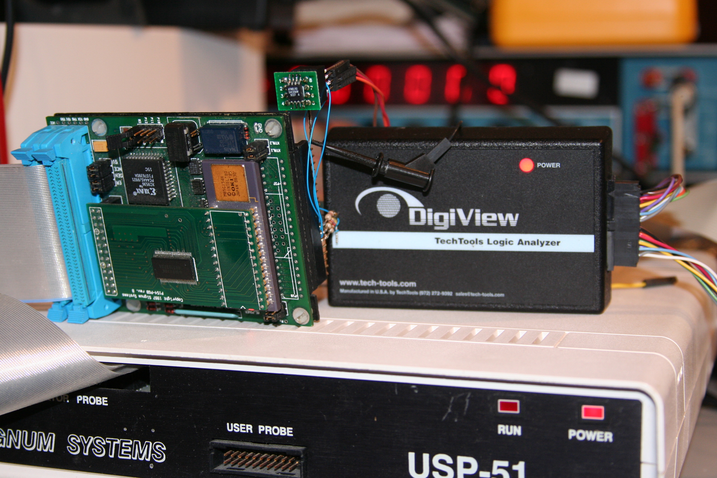
A Signum 8051 emulator was used to test the code. The logic analyzer pictures were taken using a Tech Tools Digiview USB logic analyzer.
For my tests, I used an Atmel 24C256, with a block size of 64 bytes. The data sheet can be downloaded from Atmel's web page. Using a 5V supply, this part is capable of speeds greater then 400KHz, so I was able to run my test code with without any NOPs using the Signum's default crystal of 20MHz, emulating a plain base-model 8031. I used 4.7K pull ups on SDIO, SCLK, and WP.
| I2C | EEPROM | MAIN | total | |
| Optimizer = level 1, size | 149 | 578 | 101 | 1060 |
| Optimizer = level 3, size | 129 | 524 | 87 | 972 |
| Optimizer = level 7, size | 110 | 524 | 87 | 953 |
Optimizer level #3 is really the first level (in my opinion) which is useful. Before that the compiler might do some strange things like first move a value from R5 to the accumulator, and then back again. You'll notice that the code size difference between level 3 and level 7 is only 19 bytes, that is only about 2% improvement.
The source code mentioned in this article maybe downloaded from http://www.oceanwaveconsulting.com/TaylorRiver/I2C/code/i2c.zip
While these routines exist in the public domain, re-distribution (via printed, web, email, or any other medium) may be done only by Oceanwave Consulting, Inc. or Taylor River Real Time, LLC. This source code, however, may be used in any project (commercial or otherwise), as long as the copyright and contact information are left in the source code, without modification. By using this source code, the User agrees to waive any and all claims of any nature, it may hold against either Oceanwave Consulting, Inc. or Taylor River Real Time, LLC. The User further agrees to hold harmless and indemnify both Oceanwave Consulting, Inc. and Taylor River Real Time, LLC from any and all claims by third parties relative to said use.
Nelson Chadderdon is the Vice President of Engineering of Oceanwave Consulting, Inc. Oceanwave is a small New England based embedded consulting company specializing in 8051 and TI MSP430 based projects. Oceanwave's programming philosophy is to write efficient yet easy to understand code that is easy to maintain, all while keeping your schedule. He maybe emailed at jnc@oceanwaveconsulting.com.